
Building the miniMACRO5 macro keyboard
A summary of my build log for the miniMACRO5.


Having seen this post on the mechanical keyboards subreddit I thought it looked like an interesting project, and boy do I need an interesting project during this lockdown. I ordered a couple of the PCBs[1] from the project author's store and this post describes my build journey.
What is it?
The miniMACRO5 is a macro keyboard that can have either five keys, five rotary encoders or any combination of those. Importantly the maximum number of inputs is five. Macro keyboards can be useful for specific applications, for example in Computer Aided Design to adjust zoom / pan / tilt, as the inputs are configured for particular jobs. I'll probably be using mine for volume (rotary encoder), mute, cut, copy, paste.
I ordered a set of PCBs from the author, who lives in America, and then waited for them to arrive.
Open source collaboration
Fortunately the project is open source so there's scope to collaborate. Speaking to Craig, the project's author, I found he was a pleasant chap that's happy to take questions. I've been able to submit some changes to the project and have offered him a step by step build guide via pull request. For those not familiar with open source projects, a pull request is a mechanism for offering changes to a project. If the maintainer of the main project likes your changes they can merge them into the project.
GitHub hosts the miniMACRO5 project.
Different parts and cases
I found the original build log was quite brief and as I'd never done anything like this before I needed to come to some conclusions as I was working through it. First up was a difference in parts: in the original build guide the PCB is black (mine was white) and the case was different too. Turns out my board was a version 3b, as was the top-loading case Craig had been kind enough to send me.
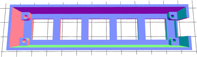
Looking at the original instructions, the case in the photo is bottom loading with holes for the switches and rotary encoders to go through. The version 3b case that I'd been sent was top loading, meaning I lowered the completed board in at the top. Version 3b also comes as two parts - a bottom "sarcophagus" and a plate that covers the board.

Reset button and Arduino headers
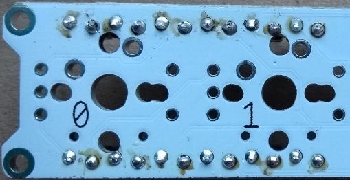
Although the reset button is optional Craig was kind enough to include a couple of switches in what he sent me. I started off by soldering this in place on the miniMACRO5's underside. This was the first time I'd soldered a component to a board, rather than just soldering two wires together or a wire to a terminal. After holding the button in place with masking tape I soldered the first pair of connections. Then I could remove the tape and solder the remaining two. I think I did a fairly neat job:
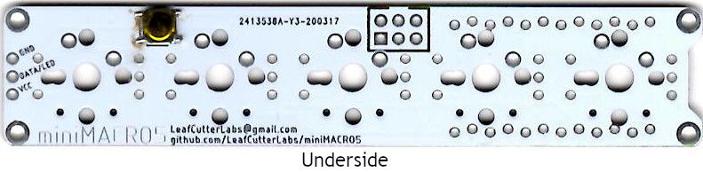
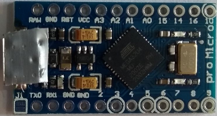
This macro keyboard is controlled by an Arduino Pro Micro which is quite a small board. Accordingly the headers for it are close together and it's necessary to solder the miniMACRO5 to each pin, avoiding any shorts. On the image above the headers get soldered into the wavy line of pins at the top and bottom right of the image. This seemed to go quite well too:
Once the connections were made I tested each with a multimeter to ensure there were no electrical shorts. All was good so I could carry on with the next stage - rotary encoders.
Rotary encoders
A rotary encoder is the sort of thing you'd use for a volume knob, which is exactly my plan here. Usually you would aim to solder components in ascending order of height (thanks for the tip Jason!) to ensure you maintained stability. Unfortunately that wasn't possible in my case because the keyboard switches are mounted through a top plate but the encoder's pins won't fit through the holes. Given the plate has to go on top of the encoder, not the other way round, I had to do things in an odd order.
Keys
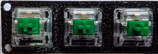
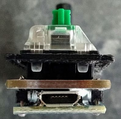
Three and five pin Cherry MX and compatible switches (e.g. Gateron) are supported by the miniMACRO5. A three pin switch has two copper contacts and a central stabilisation peg. Five pin switches have two copper contacts, a central stabilisation peg and two side pegs. Don't be fooled friends - just because there's only two contacts it's not a two pin switch!
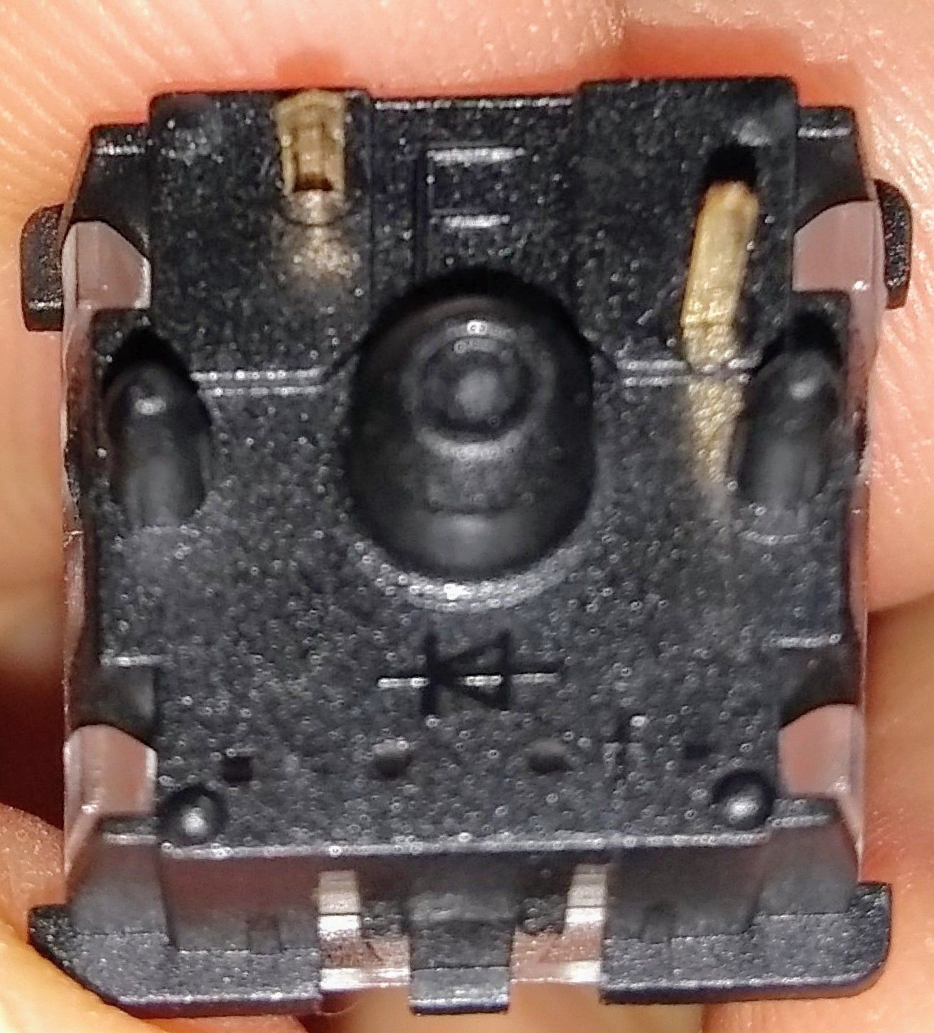
Obviously we will only be soldering the copper contacts...
I had intended to purchase Cherry MX Brown (tactile non-clicky) switches for this build, the same as my keyboard, but the switches were out of stock at Mechboards UK and I was keen to support a small UK business. Instead I opted for Gateron green switches, which while clicky isn't such a concern as I'm not typing on this macro pad. The Gateron switches were the only ones in stock at the time, and in true ironic fashion the Cherry Browns came into stock the day my Gateron Greens arrived.
Push the key switches into the plate, position on the miniMACRO5 and then solder in place. I actually have four on the macropad, I'm not sure why my photo only shows three!
Home run - add the Arduino
Once the switches were all soldered in place I checked for electrical continuity before proceeding. This was mainly because the Arduino covers two of the connections for the keys and I didn't want to have to desolder 24 pins just to fix a fault!
Once the build is complete there's not a lot of room between components, in fact some are touching. To that end it's important to insulate the USB socket:
My helping hands came in useful for holding the miniMACRO5 while I soldered the Arduino to the headers:
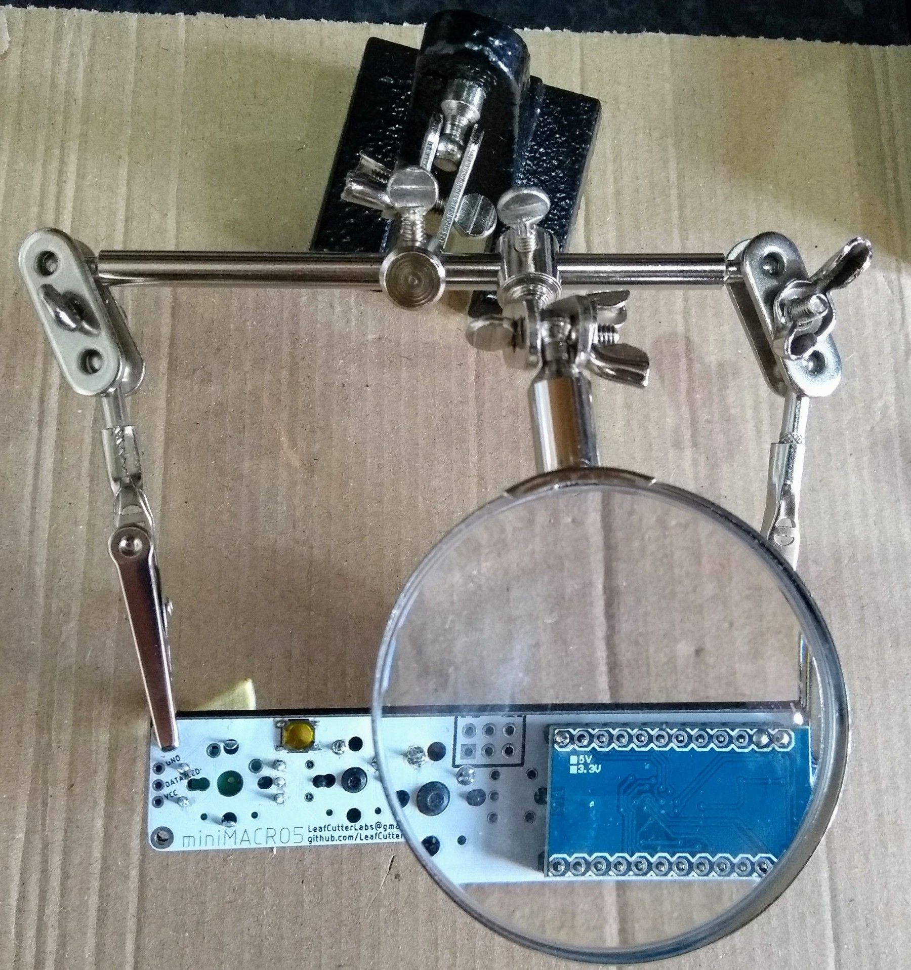
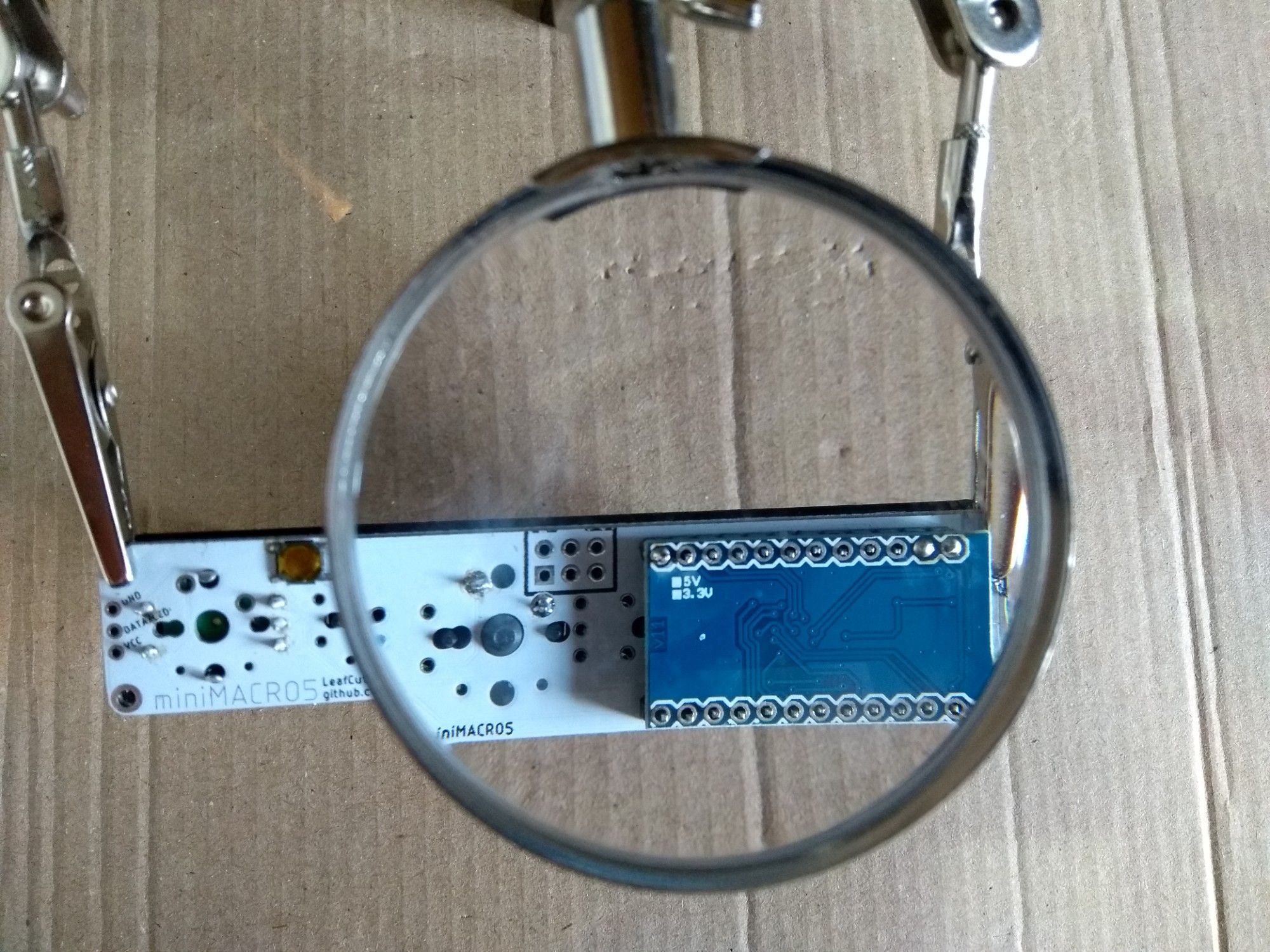
Once all the connections are made your completed build should look something like this, ready to be put into the case:
What's next?
Now the hardware is all built for the first macro pad I need to get the QMK firmware flashed onto the Arduino along with my desired configuration. The good news is that I can change the configuration if I want the board to do something different. I need to find a knob for the rotary encoder too!
I've got another board to make up and my friend Tim is kindly 3d printing me another case. I thought it would be cool to have miniMACRO5 reverse embossed on the side of the case, so I'm looking forward to seeing how that looks.
I might write a "part two" about the configuration and programming part of the project - watch this space!
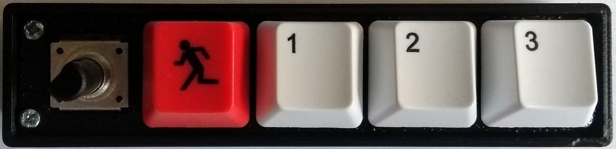
Banner image: My first (almost) completed miniMACRO5.
[1] Printed Circuit Boards